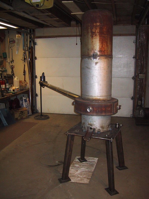
Making a Cupola Furnace
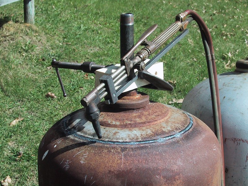
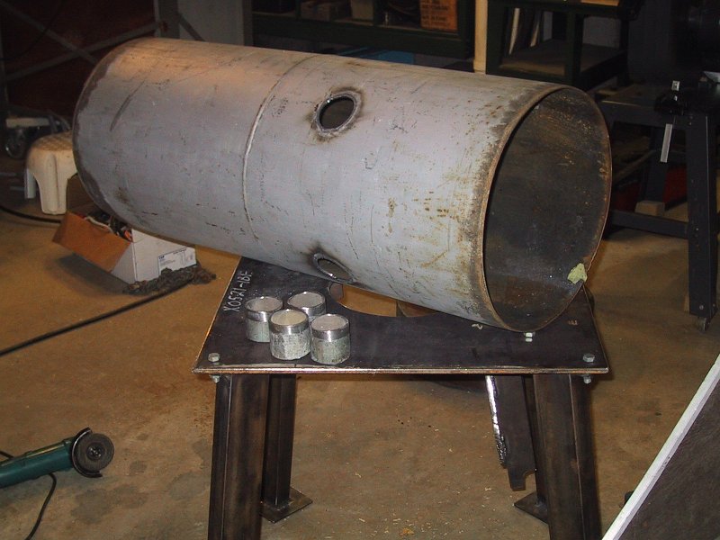
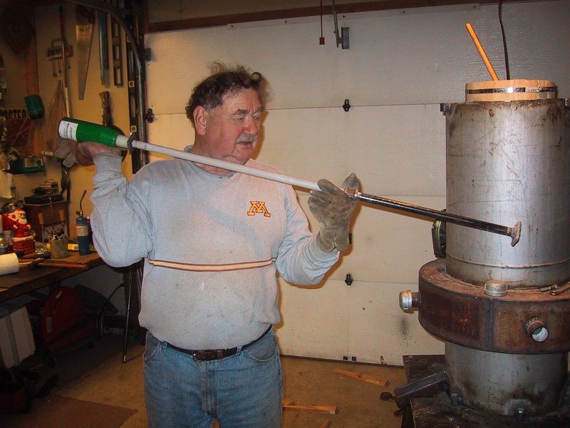
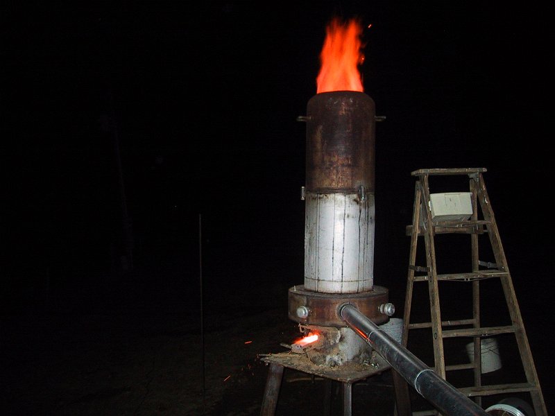
The cupola furnace
  • This picture shows the top of a discarded 100 lb. propane tank being cut off. I made a guide fixture for the cutting torch which was clamped to a block of wood. The wood block was drilled to be a close fit to fit the pipe seen screwed into the valve boss. This made an accurate circular cut.  Don't worry, the valve of the tank had been removed a year earlier and the tank was stored upside down so remaining heavier-than-air propane would have drained away. To be on the safe side, I also filled the tank with water before cutting it.
  • Here the tank with the top cut off has also been cut in half and a second tank has had the top and bottom removed. The two halves will have bolt lugs welded on to allow the two sections to be bolted together end to end.
  • The cutting torch guide is used to cut large disks out of salvaged 12 ga. steel sheet. The disks will be cut again to form rings that can be slid over the tanks. They will become the top and bottom of the "wind belt", the chamber that encircles the furnace conducting the air blast into the heat.   The steel sheet had been the sideboards on my 1940 Diamond T truck, described elsewere on this web site.
  • Here a six inch section of an unused section of tank is cut to form part of the outside of the wind belt. The tank is centered on one of the disks that is in turn centered on a Rubermaid kitchen cupboard lazy-susan. This made it easy to make an accurate parallel cut. The torch was held in place in it's clamped-down guide as the tank was turned.
  • This is a view of the torch guide, the lazy-susan, the windbelt section, and one of the disks marked for the second cut.
  • A section of 3/8" plate was cut to 24" square with the cut edges ground smooth with the angle grinder. This will be the base for the cupola.
  • That very handy torch guide is used to cut a 10" diameter hole in the 3/8" base plate. The piece that is cut out will be used as a door in the hole it was made from. This hole will be for the "dump" when the remaining coke and iron are dropped out of the furnace when the "heat" is finished for the day, a pretty spectacular event with lots of noise and sparks and heat and steam.
  • Here the legs are attached to the cupola base. They are made of 1-1/2" X 3" rectangular steel tubing with feet and mounting plates welded to the ends.
  • This is the lower section of the cupola with holes cut to accept the short sections of pipe shown along side. These sections of pipe will be welded to the tank and will protrude through the refractory lining to provide air passages called "tuyres" through which the air blast is conducted.
  • This a bottom view of the bottom dump door. It is drilled with vent holes to allow the escape of steam from the bottom of the cupola when it is first fired up. Before each heat the base of the cupola is lined with a mixture of moist clay and sand to protect it from the heat of the molten iron it will contain. This moisture is baked out when the cupola is first heated. The cupola base is fitted with sliding plate latch that can be bumped to the side to allow the door to drop free. A long bar is used to bump the latch so the door can be opened from a safe distance.
  • This is the core form that will be centered in the shell of the cupola in preparation for the ramming of the refractory. The form is made of wood strips lightly glued to the center disks and easily dismantled when the ramming is finished. The refractory starts out as a clay-like mixture but when baked at high temperature becomes capable of withstanding temperatures of up to 3,000 degrees F.
  • Here the form is inserted in the bottom half of the shell with centering wedges installed at the top. After ramming, the form will be removed and reinserted in the top half for ramming. You can see some of the mounting lugs around the top edge of the shell.
  • Here is a slab of refractory clay being split with a wide putty knife. This material is very stiff and course.
  • Here I have the "ramming" tool, a  weight from a log splitter. The weight was slammed down onto a length of steel rod with a small base plate attached to the bottom. Small bits of refractory were dropped into the form and then hammered into a continuous mass between the tank wall and the wood form. As the form filled up, a small sledge hammer topped it off. Very tiring work.
  • Here we are looking down into the cavity between the form and the tank wall at the first layer of refractory at the bottom.
  • Looking down into the cupola this photo shows the finished refractory with some of the form strips removed. The strips are numbered so they can be assembled in the same order for ramming the top section.
  • Here is the cupola assembled in the garage. The 4" stovepipe leading back and to the left conducts the blast air into the wind belt. The blast air is provided by an ebay purchased Craftsman leaf blower that blows like hell. The long pipe helps to reduce eddies in the air blast that would confuse a pitot tube (described below)  that is located close to the end of the pipe. The speed of the leaf blower motor is controlled by an electronic speed control for a router so the volume of air supplied to the blast can be adjusted. The cupola is to be used outside, away from buildings. The open top of the furnace discharges slag particles and dust. The gases discharged at the top of the furnace are around 800 degrees F.
  • Photographed near "sharpie" maker to show the size, this item made from a copper pipe is a "pitot" (pronounced "peto") tube. The device is used to measure the speed of moving air. In fact its most common use is seen as the sensing device to indicate the airspeed in aircraft. Every airplane has one. This one will be installed in the center of the airstream in the air blast tube, the pipe supplying air to the cupola. The amount of air being supplied to the blast can then be measured and monitored.
  • Here you can see a series of fine holes drilled in the circumference of the tube. This is the source of "static" air. The air rushing past the tube does not enter the tube so this becomes a source of reference pressure inside the tube which is connected to a fitting for a small plastic hose.
  • This is the "ram" air port. It is a brass fitting with a spherical shape to the end. A small square-edged hole is drilled through the fitting. A small diameter copper pipe inside the larger pipe is connected to this fitting. This pipe is isolated and sealed from the static air section of the pitot and is also connected to a hose fitting.
  • The pitot tube is a very well known device and there are tables and tables of data for designing and calibrating a pitot tube. This is another way. The speedometer on the car is a digital device that I think is pretty accurate. Speed trials in both directions on a calm day should provide accurate data. Hoses attached to the static and ram air fittings are routed to the inside of the car where they are connected to a manometer.
  • This is a photo of the manometer hanging from the rearview mirror of the car. The red liquid is water with red food coloring making it look like some real instrument. The ram air hose from the pitot tube is connected to one side of the U-tube and the static air hose is connected to the other side of the U-tube. Ram air pushes down on the ram side and the static air vents the other side to neutral pressure. The faster the air, the higher the ram pressure is and the greater is the difference in height of the two columns. There is a sliding scale in the center that is used to measure the difference in the height of water which is directly correlated (within reason) with air speed.
  • The refractory must be fired before the cupola can be used. This dries out the material and fuses it into a solid heat resisting liner. Son Scott is checking to see if the shell has warmed yet as son Steven and I look on. Kindling wood is used to light a load of charcoal that in turn ignites the coke, the fuel of the cupola.
  • Late into the evening the cupola emits fire and smoke. It takes several hours to completely cure the refractory.